catalogs
One,Product Functions and Features
Two,Product Technical Parameters
Three,Product Installation Instructions
Four,Description of the device operating interface
Five,Equipment operation process
Seven,fault resolution
Eight,Safety Precautions
Nine,Environmental Considerations
Ten,Flow rate and decomposition temperature guidelines for each material type
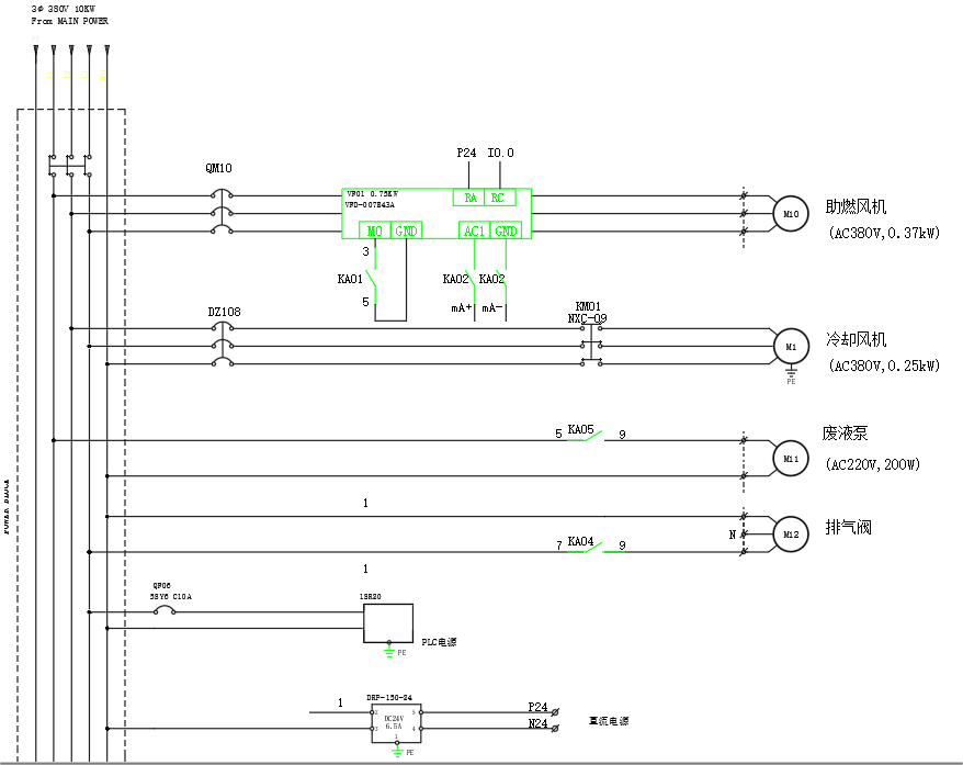
Eleven,electrical schematic
Warnings and Precautions
1. Before using this product, please read this manual in detail and strictly install the product using the specifications described in this manual.
2. This product is intended for organic liquid treatment only and is not suitable for other applications.
3. This product can only be used with liquefied petroleum gas, not natural gas.
4. Prohibit the use of the product unattended.
5. It is prohibited to disassemble the product by yourself and to use specialized parts that are not supplied by the manufacturer of this product.
6. It is prohibited to use the product in a flammable, explosive, near heat sources and humid environment.
7. It is prohibited to cover or block air vents and rupture discs with objects.
8. It is prohibited to leave the product outdoors.
9. The user must place the product in a firm and level place for use.
10. The power supply used by the user must have a reliable grounding device.
11. Each time before the official start-up must strictly check the motor, valves, sensors and air circuit and other equipment to ensure that it meets the operational requirements.
12. In the course of use, if a malfunction or abnormality occurs, immediately suspend use, unplug the power supply, and turn off the gas source. Contact the manufacturer for overhaul.
13. Handling of flammable and explosive materials is prohibited.
I. Product Functions and Features
Organic waste liquid integrated treatment equipment is a new type of organic waste liquid treatment instrument, through the safe and controllable and efficient pyrolysis technology, the waste liquid in the organic matter of more than 98% pyrolysis into harmless carbon dioxide and water, and then through the desulfurization and denitrogenation, low-temperature oxidation and other technologies of multifaceted coupling, the residual waste liquid without pyrolysis is further converted into harmless substances. The product is designed with integrated instrumentation concept and one-button safety program operation. It utilizes the exothermic decomposition of the organic waste liquid itself as most of the energy source of the treatment process, and only a small amount of external energy is needed to realize the on-site treatment of the waste liquid. It has the advantages of lightweight processing equipment, flexible processing, safe operation, high efficiency and economy, and no secondary pollution.
Second, product technical parameters
| Diethylammonium chloride | Organic waste liquid integrated treatment equipment |
| Product Model | ERME-C-5-01 |
| rated voltage | 380V 50Hz |
| rating | 1200W |
| temperature range | Normal temperature~800℃ |
| Flow range | 50~6000ml/h |
Third, the product installation instructions
3.1 Installation configuration requirements:
1) Equipped with 15Kg liquefied gas cylinder;
2) Configure 380V four-phase power supply with about 1200W;
3.2 Installation process
1) Push the unit to the designated position and then lock the wheels;
2) Connecting the LPG cylinder: screw the LPG connector counterclockwise into the cylinder port until it is tight, then open the cylinder, test the leakage with soapy water or sniff with your nose to see if there is any LPG odor, and then close the cylinder;
3) Fill the feed drum with waste liquid and insert the feed tube;
4) Plug the power cord into the main power outlet;
IV. Description of equipment operation interface
The equipment is equipped with a touch screen, providing equipment operating status, parameter setting, alarm information recording, manual control, etc..
3.1 Power-on interface

The power-on screen is the device information screen, including contact information address, etc. Clicking on the screen automatically enters the main interface.
3.2 Main interface
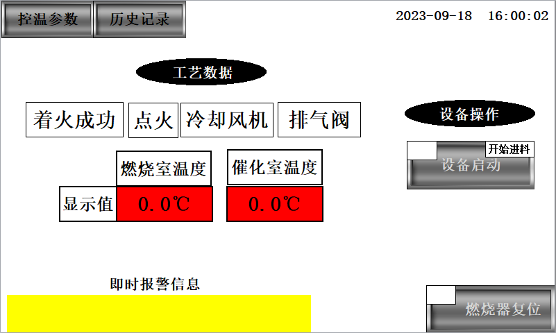
The main interface displays the time, process parameters, equipment operating status, operation buttons and alarm messages as well as access buttons for temperature control parameters and history.
The upper right corner is the entry button for temperature control parameters and alarm records, click to enter the parameter setting interface and alarm history interface respectively. The upper right corner is the time display.
In the Process Data column, the first row shows the equipment operating status, and the equipment status display is green to indicate that the equipment is operating. The second row shows the process status, recording the temperature of the combustion and catalytic chambers.
Instant alarm message field, when there is an alarm, the alarm message will be displayed and recorded within the alarm record, when the alarm disappears, the alarm message also disappears.
Inside the equipment operation column are the system startup buttons, including the equipment startup button and the burner reset button. The upper left corner of the display is green when each button is activated.
3.3 Parameter setting interface
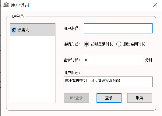
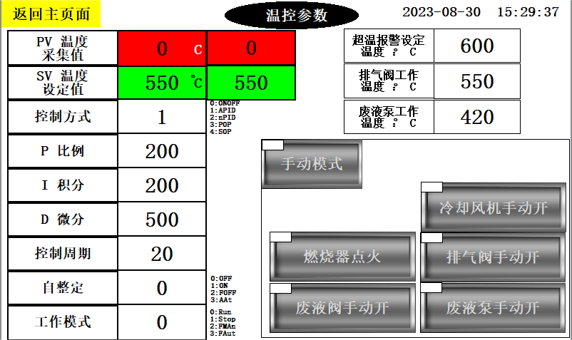
To enter the parameter setting interface, you need to click on the "Temperature Control Parameters" button in the main interface, and then a pop-up window for inputting password will appear, enter the password and enter the parameter setting interface.
The parameters that can be set mainly include the parameter values of the process and so on. In the case of use, these values are fixed parameters and are not changed after commissioning.
In addition, there is a manual startup button for the device within the parameter setting interface. When the system is down, click the manual mode button, and after the upper left side is green, you can individually and separately test to turn on each device, which is green in the upper left corner after it is turned on.
Special note: Manual mode can only be performed during a shutdown. It is not valid during automatic operation.
3.4 Alarm Record Interface
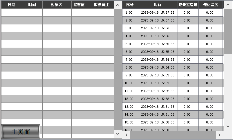
The Alarm List screen records historical fault alarm information as well as history. New alarms are displayed in red, and end alarms are displayed in black.
V. Equipment operation process
5.1 Device Startup
1. Turn on the main power air switch, turn on the main power.
2. Open the liquefied petroleum gas cylinder;
3. Insert the feed tube into the waste liquid;
4. Set the waste pump to the referenced speed;
5. System startup: Click on equipment startup, the upper left corner turns green, the system starts, the combustion chamber comes to temperature, the waste liquid pump starts for waste liquid treatment, and the start of feeding in the upper right corner turns green;
6. System stop: Click again to start the device, the upper left corner turns white, the waste liquid pump stops, the upper right corner starts to feed and turns white, the burner stops after 1 minute and the system stops;
7. Shut off the liquefied petroleum gas cylinder;
8. Turn off the main power supply.
5.2 Equipment inspection records
Daily inspection is an important work for the normal and stable operation of the facility. In the process of daily inspection, it is necessary to make a record of each process parameter, pay special attention to whether there is alarm information on the touch screen and make a record of it, when there is alarm information, please report to the relevant departments at the first time to deal with it.
Combustion system:Each time you start to observe whether instant ignition, flame color, and whether the exhaust port has black smoke, if the flame color is darker or there is black smoke in the exhaust port, stop the system in time and ask the manufacturer to come for maintenance; daily inspection, real-time observation of whether there is a flame, flame color, etc..
Fan:Daily inspection to observe the operation of the fan, whether the sound is abnormal, whether the vibration is too large, make a record.
Metering pump: daily inspection to observe the pump operation, whether the sound is abnormal, whether the vibration is too large, make a record.
Flowmeter:Daily inspection should pay attention to the waste liquid flow changes in real time, and timely adjust the flow within the normal range.
5.3 Burner reset
When the burner is faulty, burner reset is needed, click the burner reset button in the main interface, the upper left corner turns green, the burner is reset, the alarm disappears and the burner starts again.
VI. Routine maintenance
1. Nozzle:Cleaned once a week, the method is: the nozzle rod from the furnace pulled out, with a wrench to the bottom of the nozzle disassembled, soaked in ethanol placed in the ultrasonic cleaner to clean for 10 minutes, to observe the nozzle holes are clogged, such as clogging with a needle to clean up, and then installed in turn on the can be;
2. Hearth:Clean the ashes every six months, pull the ash catch tray out of the furnace chamber, pour the ashes into the garbage can using a light knocking method, and then fill it back up;
3. Catalyst:Remove the catalyst every 1 year, use light knock and hair dryer to clean, water washing is strictly prohibited, and then put it back; every 3 years, ask the manufacturer to evaluate the performance of the catalyst, according to its activity to decide whether it needs to be activated or replaced;
4. Combustion system:Have the manufacturer come in every 1 year for maintenance;
5. Instrumentation and control systems:Have the manufacturer come in every 1 year for maintenance.
VII. Troubleshooting
1. System startup anomaly:Please turn off the liquefied gas immediately, shut off the waste liquid feed, cut off the main power supply promptly and contact the manufacturer;
2. The system stops abnormally:When the system cannot be stopped, immediately turn off the liquefied gas, shut off the waste liquid feed, promptly cut off the main power supply and contact the manufacturer;
3. There was a strong odor at the site:Please turn off the liquefied gas immediately, shut off the waste liquid feed, cut off the main power supply promptly and contact the manufacturer;
4. Ignition failure:When ignition failure occurs, please press first check whether the liquefied gas is turned on, whether the liquefied gas is enough, whether the pressure gauge is 0; then check whether the combustion fan is rotating; whether the igniter is green; whether the gas valve is open. Confirm one by one and then restart the system, if it still malfunctions, please contact the manufacturer;
5. Furnace over-temperature alarm:First check whether the spray liquid volume exceeds the normal value, reduce the spray liquid flow rate, if the alarm is not eliminated, stop the system immediately and contact the manufacturer;
6. Failure of the wind turbine:Blower not turning, excessive sound, excessive vibration, contact manufacturer;
7. Instrumentation:The meter display is abnormally high or low, contact the manufacturer.
VIII. Security considerations
Please read the operating instructions carefully to prevent personal injury as described below:
1. Electrocution: Failure of the operator to operate in accordance with electrical work safety regulations for unauthorized operation, lack of general knowledge of safe use of electricity or malfunctioning of the electrical equipment itself may result in electrocution accidents. When conducting facility operations and inspections. If you find leakage of electricity, no response from electric equipment, or abnormal operation of electrical components, please immediately turn off the liquefied gas, shut down the waste liquid feed, promptly cut off the facility's main power supply, and contact our professional staff withUnauthorized disassembly and repair is strictly prohibited!!!!
2. Mechanical injuries:Fan and other moving parts if the protective facilities defective or overhaul after not re-installed protective cover, the operator inadvertently contact with high-speed operation of moving parts such as flywheel, coupling, can cause the operator by collision, involved in the risk of injury. In the operation of the facility, the operator should maintain a certain distance between the body and the fan, inspection of the fan in the startup whether there is a strange sound!!!!
3. Burning:The equipment is high-temperature equipment, and its piping and furnace chamber have been insulated. In order to protect personal safety, it is strictly prohibited to touch its furnace chamber and piping when the facility is in operation.
4. Object strikes:If the rotating moving parts of mechanical equipment are cracked or mechanically damaged and not replaced in a timely manner, the broken parts may be thrown out due to the inertia of high-speed rotation, which can cause object striking injuries.
Operators found any pipeline, valve, equipment, instrumentation with abnormal conditions, should immediately stop all operations of this facility, cut off gas and electricity, the first time to contact the manufacturer, is strictly prohibited unauthorized maintenance!!!!
5. Noise and vibration:Fans are a strong source of noise and vibration, and the noise and vibration generated during operation can cause certain occupational hazards to the operators. Operators should wear earplugs in accordance with relevant national regulations during inspections, and close contact with the fan is strictly prohibited when the fan is started!!!!
IX. Environmental considerations
The main sources of pollution and contaminants in this equipment:
(1) Wastewater: no wastewater.
(2) Exhaust gas: This facility is an exhaust gas treatment system and does not produce exhaust gas.
(3) Solid waste: waste catalyst and waste slag, disposed of in accordance with the law.
(4) Noise: The noise generated complies with the requirements of the factory noise standards for industrial enterprises.
Ten, each species of material flow rate and decomposition temperature guide
| Material Variety | pump speed | decomposition temperature |
| Water content greater than 80% material | 450~550rpm/min | 550°C |
| Water content 50%~80% material | 400~500rpm/min | 550°C |
| Water content 10%~50% material | 400~500rpm/min | 550°C |
| 90% Alcohols | 150~200rpm/min | 500°C |
| 90% Ester | 150~200rpm/min | 500°C |
| 90% Aliphatic hydrocarbons | 150~200rpm/min | 500°C |
| 90% Aromatics | 150~200rpm/min | 500°C |
| 90% Halogenated hydrocarbons | 150~200rpm/min | 500°C |
| 90% Ketones | 150~200rpm/min | 500°C |
| Lubricating oil type (need to be heated to 40~50℃ for feeding) | 150~200rpm/min | 500°C |
Note: This value is only a reference, the user needs to adjust the temperature of the furnace according to the actual operation, in order to achieve the best results!
XI. Electrical schematic diagram